Unified Modeling Language (UML) is a standardized visual language used in software engineering to describe, specify, design, and document the architecture of software systems. It provides various diagram types, including class diagrams (to show system structure), use case diagrams (to illustrate user interactions), sequence diagrams (to detail object interactions over time), and activity diagrams (to represent workflows).
UML helps developers and stakeholders visualize system components, their relationships, and behaviors, facilitating better understanding, communication, and collaboration in software development projects. It enhances the clarity of system design and supports the creation of scalable, maintainable software.
When designing a class, creating a UML diagram can be very useful. UML offers a standardized way to visually represent object-oriented systems. As shown in the following figure, a UML class diagram is a box divided into three parts. The top part contains the class name, the middle part lists the class's data attributes, and the bottom part lists the class's methods.
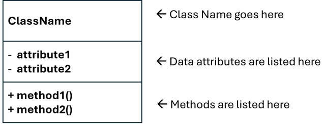
- Class Name: The top section is for the name of the class.
- Attributes: The middle section lists the class's data attributes.
- Methods: The bottom section lists the class's methods.
Example Class Diagrams
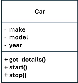
Car Class
- Class Name: Car
- Attributes: make, model, year
- Methods: get_details(), start(), stop()
|
|
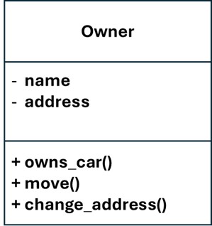
Owner Class
- Class Name: Owner
- Attributes: name, address
- Methods: owns_car(), move(), change_address()
|
|
To summarize, a UML class diagram visually represents a class by dividing it into three sections: the class name, its data attributes, and its methods. This structure helps in clearly organizing and presenting the class's components, making it easier to understand and design object-oriented systems.